PhotoSauce Blog

0 Comments

In my last post, I detailed most of the Graphics class settings/values and some tips for getting the best balance of performance and quality. In this post I’ll be examining the InterpolationMode values in detail. The short version of this post is that if you want to get the best quality from System.Drawing/GDI+, use InterpolationMode.HighQualityBicubic. But if you’re curious as to what that means or what the other values mean, read on.

I won’t be doing sample comparisons of the various interpolators’ output because that’s already been done, and I don’t have much to add to that. This is more of a technical analysis of the exact implementations and parameters used and how they compare with the standard definitions of those algorithms.

This post assumes you have a basic understanding of image resampling algorithms and want to see what the GDI+ implementation actually does compared to other software. If you’re not familiar with image resampling terminology or methods, I’d suggest starting with Jason Summers’ excellent article “Basics of Image Resampling”. Once you’ve read that, you may also find his “What is Bicubic Resampling?” enlightening. And if you want to completely geek out on the various standard interpolation algorithms, you can’t go wrong with ImageMagick’s Resampling Filters page. I’ll be linking to that one a lot as I go through the individual interpolators. They have detailed explanations and sample images to go with most.

For my analysis of the GDI+ implementation, I’ll be using the ResampleScope utility, also by Jason Summers. It’s a great piece of software. If he had a donate button on his site, I’d totally click it.

InterpolationMode.NearestNeighbor

There’s not much to say about this one nor I can I show a graph of it like I will with the rest. It’s the fastest and lowest quality interpolator available. Also sometimes referred to as a Point Filter, it simply maps each pixel in the destination image to the nearest corresponding pixel in the source image. The results will be blocky, but when dealing with enlargements of a blocky source, that may actually be desirable. It shouldn’t be used for downscaling. The GDI+ implementation is completely standard and its output matches my implementation in MagicScaler pixel-for-pixel.

InterpolationMode.Bilinear

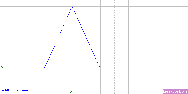
The Bilinear (also commonly known as Linear, Tent, or Triangle) interpolator is another completely standard implementation. As long as you’re enlarging, that is…

rsgdilin

Yep, that’s a perfectly normal Triangle Filter, all right.

These graphs are fairly large, so I’m showing them at half size.  You can click the images to embiggen them if you like.

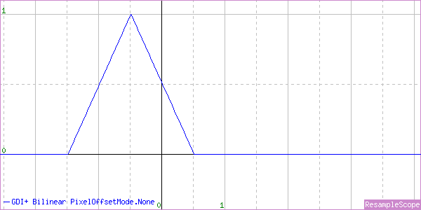
One of the neat things about ResampleScope is that it will also show you when the sample points are calculated incorrectly. For example, if I set the GDI+ PixelOffsetMode to None, here’s what the graph looks like:

rsgdilinoff

The shape is right, but it’s not centered at 0, so it will shift the image up and left. We saw that in the previous post. I’ll be using the correct PixelOffsetMode.Half from now on. I just wanted to show that once. An eerily similar graph will appear in my upcoming breakdown of the WIC interpolators as well.

The documentation for InterpolationMode has an interesting note for the Bilinear value.

“This mode is not suitable for shrinking an image below 50 percent of its original size”.

Let’s see why that is, shall we?

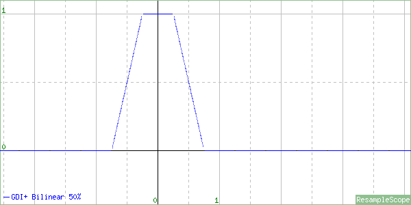
rsgdilin50

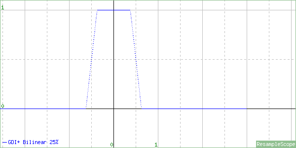
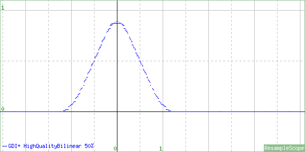
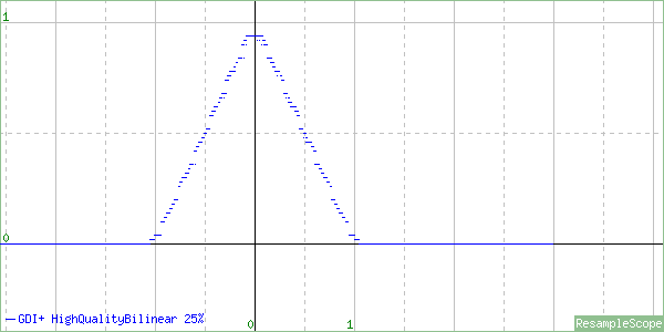
This graph is from a resize to 50% of the original size. Notice that we no longer have a triangle. The top is cut off, plus it’s squished in at the bottom. In a properly implemented scaler, we would expect that the shape of the graph would be the same regardless of the resize direction or ratio. Here’s the graph for a resize to 25%

rsgdilin25

Essentially, this interpolator is devolving toward a Box Filter the more we shrink the image. This interpolator will produce aliased output. That’s what happens when the edges of the sample range (also known as the filter support) don’t extend to at least ~.75px in each direction, which is about where it was on the 50% shrink. This interpolator is fine for enlarging, but you probably don’t want to use it for shrinking unless speed is more important to you than quality.

InterpolationMode.Bicubic

Having gotten a taste of the Bilinear interpolator, I think I can guess what we’re going to see with Bicubic. We’ll jump straight into the graphs.

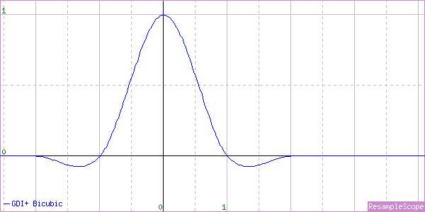
rsgdicub

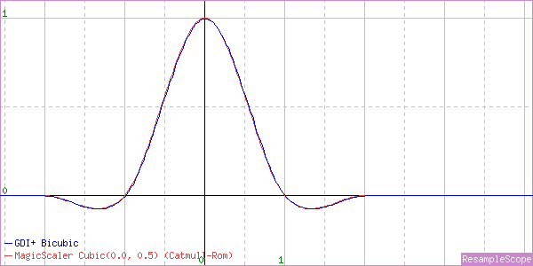
For enlarging, we have a perfectly normal Cubic Filter. I can compare the shape of the curve to that of a known configuration from MagicScaler to get a more precise definition. ResampleScope lets me overlay those together to compare them easily. This one is a near-perfect match for the MagicScaler implementation of the Catmull-Rom (B=0, C=0.5) Cubic – a nice choice.

rsgdimagcub

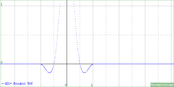
Let’s see what happens when we shrink to 50%.

rsgdicub50

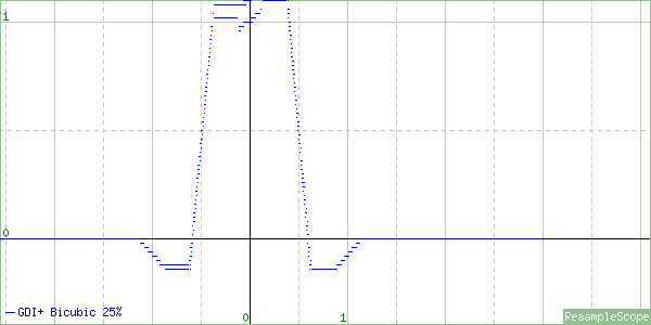
Gross. That’s no good for nobody. And 25%?

rsgdicub25

Also gross. In the docs for this one, there’s a note saying it’s unsuitable for shrinking below 25%, but I’ll just go ahead and say this one’s really unsuitable for shrinking at all. In fact, this one is worse than Bilinear for shrinking. It will, however, give nicer, sharper results for enlargements.

InterpolationMode.HighQualityBilinear

What we’ve seen so far are quite standard implementations of well-known resampling algorithms that simply aren’t scaled fully for shrinking images. That makes them faster, but they sacrifice quality. We can probably assume that the HighQuality variants are correctly scaled, though. The documentation has the following note on both of the HighQuality options:

“Prefiltering is performed to ensure high-quality shrinking”.

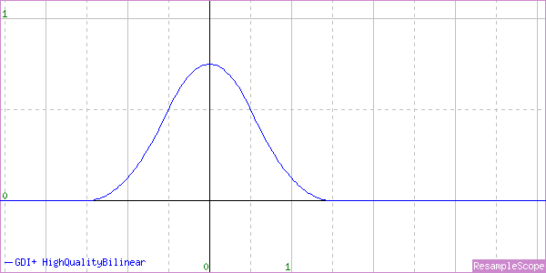
That’s vague and mysterious, but let’s see what the graphs say, starting with an enlargement.

rsgdihqlin

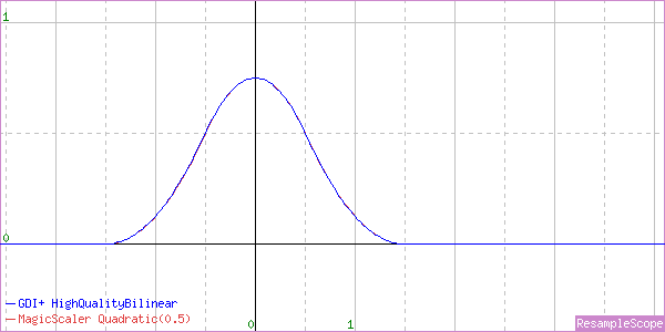
Well, that’s interesting… It’s not even close to linear. It looks more like a Quadratic Filter, and sure enough it’s a dead ringer for MagicScaler’s Quadratic implementation with its blurriest setting.

rsgdimaghqlin

But the real test is the downscaling, so let’s see what happens there.

rsgdihqlin50

Much like the low quality modes, at 50% it appears to be just squeezing the filter in, although it still has a large enough support range to give good quality at this size. Let’s see 25%.

rsgdihqlin25

What do you know… it appears to be converging on an actual Linear filter.

So it turns out the HighQualityBilinear filter is actually a blurry Quadratic for enlarging and minor shrinking but becomes a Linear for higher-ratio shrinking. This is a perfectly cromulent interpolator. It’s suitable for all uses as long as you don’t mind the blurring.

As for the prefiltering they mentioned, the discontinuities in the graph may be a reflection of that. ResampleScope will sometimes show gaps in the graph for higher-ratio shrinking, but the gaps in these graphs are abnormally large. My guess is they’re doing a blur before resizing. You can approximate a correctly scaled resampling filter by blurring the source image first and sampling a smaller range. They may be doing that instead of scaling the filter up all the way. The results end up similar, so I’ll take their word for it. That may also be a clue to the poor relative performance of this interpolation mode. In my testing, it has often been slower than HighQualityBicubic despite the fact that it has a smaller sample range.

InterpolationMode.HighQualityBicubic

We already know this is the best one, but let’s see what it actually does. As before, we’ll enlarge first.

rsgdihqcub

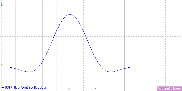
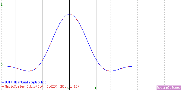
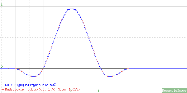
We would normally expect a Cubic to have a support of 2px, and this one reaches just beyond that. The closest match I could find with MagicScaler was a nonstandard Cubic (B=0, C=0.625) with a blur factor of 1.15, which means the normal sample range is simply stretched by 15%, giving a smoothing effect.

rsgdimaghqcub

The blur factor will soften edges when enlarging, which can prevent aliasing, so that’s not a bad choice. In fact, This is actually very similar to PhotoShop’s Bicubic Smoother resizing mode. Here’s a shrink to 50%.

rsgdimaghqcub50

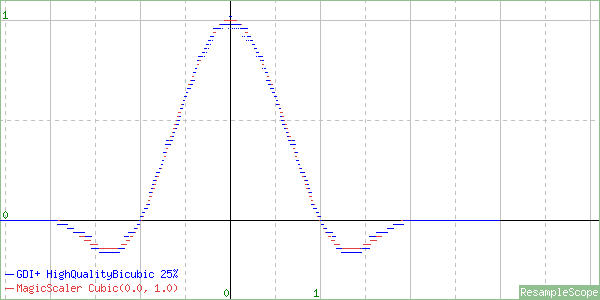
This one looks more like a Cardinal Cubic (B=0, C=1), which can cause some ringing artifacts, with a very slight blur factor of 1.025 balancing that out. And finally a shrink to 25%…

rsgdimaghqcub25

On this one, the blur factor is gone, and we’re left with just a Cardinal Cubic. That seems to hold up at more extreme downscale ratios as well. Again, it sharpens more than some people would prefer and can cause some ringing and moiré, but it’s a correctly-implemented interpolator. It’s certainly the best GDI+ has to offer for shrinking.

Once again the the slight discontinuities in the graphs indicate there may be a pre-blur at work, but they match the reference curves closely, so the results will be very close to correct (for this algorithm).

The Others

Now that we know what all the explicitly named interpolators actually do, it’s a simple matter of comparing the graphs to put real names to the generic ones. Why the docs don’t do this is beyond me, but here goes…

InterpolationMode.Default = InterpolationMode.Low = InterpolationMode.Linear

InterpolationMode.High = InterpolationMode.HighQualityBicubic

That’s it?

Pretty much. GDI+ obviously has a limited selection of interpolators, and the tradeoff in speed between the Default/Low/Linear and the High/HighQualityBicubic is quite dramatic. Adding to that speed difference is the fact that both of the HighQuality interpolators require that the input image be converted to RGBA format for processing, while the Linear interpolator is able to process in RGB mode directly. If you think about resizing a high-res file, that conversion cost could be quite high, not to mention the work done by the interpolator itself. It’s not uncommon in cases of extreme downscaling to use a hybrid approach, where the image is downscaled to an intermediate size using a faster/lower-quality interpolation and then finished off with a high quality interpolator to get to the final size. In fact, MagicScaler does just that with its hybrid scaling modes. Photoshop does too. I didn’t bother implementing that in my reference resizer, but if you’re stuck with GDI+, it might be worth a try for you.

So there you have it… more than you probably ever wanted to know about GDI+’s interpolator implementations. This info will come in handy when comparing GDI+ with MagicScaler, though, as we want to make sure we’re doing the same work in both. Wouldn’t be fair otherwise, would it?

In the next and final installment, I’ll be going over the image ‘validation’ in System.Drawing and looking a bit further into that RGBA conversion I mentioned for the HighQuality interpolators.
0 Comments

In my last post, I covered some of the high-level features in my reference System.Drawing/GDI+ resizer. In this post, I’ll be discussing some of the options on the Graphics and ImageAttributes classes that affect the image quality and scaling/rendering performance of Graphics.DrawImage(). I’ve seen a lot of misinformation around the web when it comes to these settings, some of it even coming directly from MSDN. The GDI+ documentation is much more complete and accurate than the documentation for the System.Drawing wrappers, but even then, some of the concepts can be foreign to developers without a background in image processing. I’ll attempt to describe them better and with concrete examples.

The important thing to take away from this is that each of these settings and its corresponding values are designed to address a specific facet of image quality. There’s no secret combination that unlocks image processing nirvana. If quality is your only concern, you can set all the HighQuality options and know you’re getting the best GDI+ can do, but you’ll pay an unnecessary performance penalty (we saw examples of that in Part 1 of this series). If you want the best quality with the best performance possible, you’ll need to learn what the options do individually so you know when and how to use them. There actually aren’t that many.

Graphics.InterpolationMode

This setting is the most important and perhaps the least understood, so there’s a lot to say here. I’ll be doing an entire post on it, in fact (I know, I’m a tease). For now, I’ll just say that unless you have a good reason not to, you should always use InterpolationMode.HighQualityBicubic, which is the highest quality interpolator available in GDI+. It’s also the slowest, but you get what you pay for…

ImageAttributes.SetWrapMode()

One of the more common complaints you’ll see about DrawImage() is that it produces artifacts around the edges of images. I can show my own example of the artifacts in question by resizing a solid grey image using InterpolationMode.HighQualityBicubic and the default values for the remainder of the settings on the Bitmap and Graphics objects. I opened the resulting image and zoomed in (15x) on the corner.

wrapmode

You can see two things going on here. First, the outermost edges have the transparency grid showing through in my viewer, so they’re not completely opaque, which is strange considering the original image didn’t have an alpha channel. Second, there is a lighter 1 pixel wide line set 1 pixel in. That lighter color also doesn’t appear anywhere in the original image. Note that if I saved this image in a format that didn’t support transparency (like JPEG), the semi-transparent pixels would be blended with black instead and would show up darker grey. That was the complaint in the stackoverflow question I linked above.

What we’re seeing in this case is the result of several factors.

  1. GDI+ starts with a blank (transparent or black – depending on your PixelFormat) canvas and draws your resized image on top of that.
  2. The HighQuality scalers in GDI+ do their image scaling in RGBA mode, even if neither your source nor destination image is RGBA.
  3. GDI+ doesn’t handle edge pixels correctly by default.
  4. The HighQualityBicubic interpolator has sharpening properties.
  5. GDI+ doesn’t handle sharpening with transparency correctly.

There’s nothing you can do about the first two points. That’s just how DrawImage() works.

The last two points are the cause of the lighter lines, and they can be negated by using a non-sharpening interpolator. Here’s the same image resized with the HighQualityBilinear interpolator, which smooths rather than sharpens. The lines have been eliminated, but the semi-transparent edge pixels remain.

wrapmodelinhq

Finally, if we use the plain Bilinear interpolator, which has a smaller sampling range, we get the solid image we expected.

wrapmodelin

Yeah, I know… I said to always use HighQualityBicubic…

The reason using a lower quality interpolator fixed the issue is the third point I mentioned above. GDI+ doesn’t handle edge pixels the same way most image scalers do. Imagine your source image is sitting in the middle (if there is such a thing) an infinite transparent plane. During the resize, any time the interpolator tries to sample pixel data that falls outside the bounds of the original image, it has nothing but transparent pixels to use. Both of the HighQuality interpolators in GDI+ use convolution kernels that require pixels from beyond the image edges. Most image scalers will simply extend the edge pixels outward to get the correct results, but GDI+ doesn’t do that. To get the desired behavior, you must use an overload of DrawImage() that accepts an ImageAttributes object.

ImageAttributes has a WrapMode property that allows you to tell GDI+ to tile the input image across that imaginary infinite plane to fill in the pixels beyond the edges. The closest you can get to a normal implementation is to mirror the edge pixels in all directions, by using ImageAttributes.SetWrapMode(WrapMode.TileFlipXY). This ensures that there are always valid pixels to sample, and you’ll get the expected behavior for the edge pixels. Don’t worry, it’s not as expensive as it sounds, and the quality tradeoff is worth it. I won’t bother with a sample image… it’s just a grey square like the one above, as you’d expect, no matter which interpolator you choose.

My point about GDI+ not handling sharpening with transparency correctly still stands, though. If your image contains a transition from transparent to opaque somewhere in the middle of the image, you’ll get the same type of artifacts we saw above, and the WrapMode won’t help you, because the edge pixels aren’t the issue. Below is the result when resizing an opaque grey square surrounded by a transparent border. Here I’ve used InterpolationMode.HighQualityBicubic with WrapMode.TileFlipXY.

wrapmodemid

You can see the artifacts are back, now appearing in the middle of the image instead of on the edge. There’s no complete fix for that (see the next section for a partial fix), other than to use a non-sharpening interpolator… or to use a different scaler (like MagicScaler) that handles sharpening and transparency correctly.

Graphics.PixelOffsetMode

Looking at the System.Drawing docs, it appears you have five settings available for PixelOffsetMode. They make some vague references to a tradeoff between quality and speed to differentiate them, and they even manage to get those wrong. Contrast that with the GDI+ docs for the same setting. Those docs make it clear; there are really only two options, and the Remarks section describes quite nicely what each does. The real options: None and Half. The rest are just aliases for those two. I’ll make it even simpler: None=Bad, Half=Good. The default value is Bad. While there may technically be a performance difference between the two, it’s not measurable. The quality difference most certainly is. In the following example I have resized a 3x3 pixel checkerboard grid to 100x100 using the NearestNeighbor interpolator, first with the default mode and then the correct one.

offsetmodewrong offsetmoderight

The results speak for themselves. You should always set the PixelOffsetMode to Half or HighQuality (same thing) when using DrawImage().

That said, I have to admit that my examples from the section on WrapMode used PixelOffsetMode.None to accentuate the artifacts. Had I used Half/HighQuality, the artifacts would still be present, but they would be more faint. Here are those two examples redone with PixelOffsetMode.Half. In order to show the edge artifacts in the first image, I have not set the WrapMode.

wrapoffedge wrapmodecomp

Again, setting both PixelOffsetMode.Half and WrapMode.TileFlipXY gives you the best quality GDI+ has to offer. That will completely correct the artifacts at the image edge and will give the result above on a hard transition from transparent to opaque away from the edge. Depending on your viewing environment, the artifacts in that one may be quite difficult to see now. If you can’t see them, just take my word for it; they’re there.

Graphics.CompositingMode

This is an interesting one in that the default value (CompositingMode.SourceOver) is the more expensive option. Every other Graphics setting defaults to lower quality/higher speed. SourceOver is what you want if you’re actually blending multiple layers, but you’ll incur an unnecessary performance hit if you’re not. In a simple image resizing scenario, you’re compositing the resized image over a blank background, so there’s no need to calculate any blending between those layers. You can, in these cases, set the value to SourceCopy (which simply overwrites the bottom layer with the top) to get better performance. If, however, you’re applying a background matte to a partially transparent image, drawing text over an image, or blending multiple images together, you’ll want to use the default value of SourceOver.

In my reference resizer, to maximize performance, I set the value to SourceCopy by default and switch to SourceOver only if matting is requested.

Graphics.CompositingQuality

This one is my favorite, if only because this is the setting that I read the most crazy things about on teh internets. It can also be a big performance killer.

Much like PixelOffsetMode, there’s a gulf in quality between the System.Drawing docs and the GDI+ docs for CompositingQuality. The .NET documentation again presents you with five options and only vague comments about speed vs. quality to help you choose between them. The Remarks are even worse on this one, claiming differences in performance and quality between two aliases for the same value. They also say something about surrounding pixels being taken into account, which is complete nonsense. The GDI+ docs are much more clear about what the real options are and what they actually do. In this case, as before, there are really two options: AssumeLinear and GammaCorrected. AssumeLinear=Bad, GammaCorrected=Good. The default is Bad. See this MinutePhysics video for a simplified explanation of the difference. The math is dumbed down in the video, but you’ll get the idea. The real math can be found in the sRGB spec if you’re interested.

For my example, I’ll blend green and red as they do in the video so you can see the effect. I start with an image that has a gradient from green to transparent (shown here over a transparency grid). I then matte that over a red background to see how they blend.

compmodebase compmodewrong compmoderight

Note that the image on the right blends smoothly (Good) while the middle image shows a dark, muddy line where the colors blend (Bad).

The trick in this case is that doing gamma-corrected blending is much more expensive than doing it the wrong way, so the speed vs. quality tradeoff is very real this time. When using CompositingMode.SourceOver with CompositingQuality.GammaCorrected, you will have a measurable performance hit. Again, in my reference resizer, I apply those settings only if a matte is being applied to a partially transparent image. For normal image scaling, there’s no need; you’ll only be slowing things down, potentially a lot.

Bonus: Graphics.SmoothingMode

Unless you’re drawing vector shapes on top of your image, this setting has no effect. It doesn’t affect DrawImage(), nor does it affect text rendering. I see lots of developers including it in their image resizing code, but for the most part, they’re just wildly setting anything with HighQuality in the name because the documentation does such a poor job of explaining what the settings actually do, and they can’t be bothered to dig deeper. It’s not harmful; it’s just a throwaway line of code for the cargo cult. My reference resizer does no drawing, so it doesn’t set a SmoothingMode.

Tune in next time for my detailed examination of the GDI+ InterpolationMode values.

Questions? Suggestions? Sound off in the comments.